One cable between two switches is one point of failure. Add a second cable and you have redundancy, but Spanning Tree quietly blocks it, so you paid for a link that carries nothing. EtherChannel fixes that: it bundles the cables into one logical link, keeps both working, and survives the loss of either one. LACP is the open standard that negotiates the bundle safely.
This guide is for network engineers who already know VLANs and trunks. We recap redundancy first, then cover how EtherChannel and LACP work, build four topologies in Cisco Packet Tracer 8.2.1, break them on purpose, and finish with a campus try-out project you can submit for marking. Keep Packet Tracer open beside this page.
- Redundancy recap
- How EtherChannel and LACP work
- Load balancing
- The labs: Topologies A, B and C, then fault injection
- Design rules
- Commands and flags
- Try-out project (Topology D)
- Your submission
- Sources
Redundancy recap
Redundancy means no single failure takes users offline. In a switched network it shows up at three levels:
- Link redundancy: more than one cable between two devices.
- Device redundancy: more than one switch or router in a role, for example two distribution switches.
- Path redundancy: more than one route through the network, handled by STP at Layer 2 and routing protocols at Layer 3.
Ethernet frames have no TTL, so a physical loop floods the network. STP prevents that by blocking redundant ports, which is why a second cable between two switches sits idle (my STP and RSTP lab shows this in detail). You keep the backup, but you lose the bandwidth. EtherChannel gives you both: the two cables become one logical interface, STP sees a single port, and nothing is blocked.
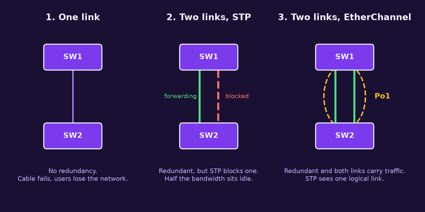
One limit up front: EtherChannel protects against a link failing. If SW2 itself dies, the bundle dies with it. Device redundancy needs a second switch, and bundling across two switches needs stacking, VSS or vPC style features that Packet Tracer does not model.
How EtherChannel and LACP work
EtherChannel bundles up to eight compatible physical ports into one logical Port-channel interface. Physical ports are the members. Configuration applied to the Port-channel (trunk mode, allowed VLANs, STP settings) is pushed to all members, so you configure the logical interface and not the members individually. Cisco states this directly in its Catalyst 2960 guide, and it is the root of most mistakes.
| Fact | Value | Source note |
|---|---|---|
| Members per bundle | Up to 8 active. LACP allows 16 configured, 8 active and 8 hot-standby | Cisco 2960 guide |
| Bundles per switch | 6 on the older 2960 images in that guide. Check your platform | Cisco 2960 guide |
| Must match on all members | Speed, duplex, native VLAN, allowed VLAN list, trunk mode | Cisco 2960 guide |
| Layer | Layer 2 (access or trunk) or Layer 3 (routed, on multilayer switches) | Cisco docs |
| STP view | One port, the Port-channel | Cisco 2960 guide |
Three ways to form a bundle
| Mode | Keyword | Protocol | Notes |
|---|---|---|---|
| LACP | active / passive | IEEE standard, any vendor | Negotiates and checks members. Use this by default. |
| PAgP | desirable / auto | Cisco proprietary | Cisco to Cisco only. |
| Static | on | None | No negotiation, no safety net. Both ends must be on. |
LACP is defined in the IEEE standard that began as 802.3ad and now lives in 802.1AX. Switches exchange LACP packets, learn each other's identity and port capabilities, and group only ports that match. If a member stops matching or the partner stops answering, it is removed instead of silently misbehaving. That check is why I prefer LACP over on.
Which mode pairs form a bundle
| One end | Other end | Result |
|---|---|---|
| active | active | Bundle forms |
| active | passive | Bundle forms |
| passive | passive | No bundle. Nobody starts the conversation |
| desirable | desirable or auto | Bundle forms (PAgP) |
| auto | auto | No bundle |
| on | on | Bundle forms, no checking |
| active or passive | desirable, auto or on | No bundle. LACP and PAgP do not interoperate, and on only pairs with on |
LACP picks its decision maker by priority: the switch with the lower system priority (default 32768), then the lower MAC address, decides which ports are active. Each port also has a port priority (default 32768, lower wins). You only touch these when you configure more links than can be active at once, so the extras become hot-standby. In show etherchannel summary, a standby member shows the flag H.
Load balancing
A bundle does not split each packet over both cables. The switch hashes part of the frame (MAC or IP addresses) into a number that picks one member, so one conversation always uses one member and arrives in order. Two consequences follow:
- A single flow can never go faster than one member link. A 2 x 1 Gbps bundle does not give one download 2 Gbps.
- Balance depends on variety. If all traffic has the same addresses, the hash always picks the same link. Cisco's own example is an access switch sending to one router: source-based hashing spreads it, destination-based would not.
The method is global to the switch, set with port-channel load-balance. On the 2960 the default is src-mac.
| Method | Hashes on | Good for |
|---|---|---|
src-mac | Source MAC | Many hosts behind an access switch sending to a few destinations |
dst-mac | Destination MAC | Traffic fanning out to many destinations |
src-dst-mac | Both MACs | Unsure which side varies |
src-ip / dst-ip | Source or destination IP | Routed traffic where MACs repeat |
src-dst-ip | Both IPs | Usually the best spread on distribution links |
Packet Tracer 8.2.1 notes
Download Packet Tracer from the Cisco Networking Academy resource hub. You sign in with a NetAcad or SkillsForAll account. Cisco's Packet Tracer help lists EtherChannel, LACP and PAgP among the supported switching protocols. Treat it as a simulator of IOS behaviour, not a copy. Some show commands, flags and timings can differ from real Catalyst switches, so I mark every output below as an example.
Devices used: 2960-24TT (two Gigabit uplinks, 24 FastEthernet) and 3560-24PS (multilayer, 24 FastEthernet and two Gigabit). Use Fa or Gi ports exactly as the diagrams say, and stay at three bundles or fewer per switch.
The labs
Checkpoint
Why does a second cable between two switches often carry no traffic?
STP blocks one of the two ports to prevent a loop, so the second link is a standby.
What does STP see when two links are in a Port-channel?
A single logical port, so nothing needs to be blocked.
Which LACP mode pair will never form a bundle?
passive with passive, because neither end starts negotiation.
Topology A: two switches, from the problem to the bundle
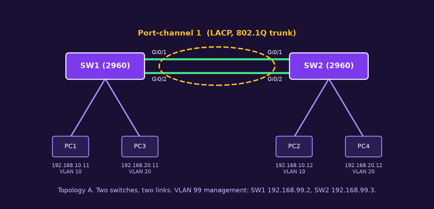
A1. Build the VLANs and observe the problem
Configure both switches (use SW2 and its own address on the second):
Switch> enable
Switch# configure terminal
Switch(config)# hostname SW1
SW1(config)# vlan 10
SW1(config-vlan)# name STAFF
SW1(config-vlan)# vlan 20
SW1(config-vlan)# name LABUSERS
SW1(config-vlan)# vlan 99
SW1(config-vlan)# name MGMT
SW1(config-vlan)# exit
SW1(config)# interface FastEthernet0/1
SW1(config-if)# switchport mode access
SW1(config-if)# switchport access vlan 10
SW1(config-if)# interface FastEthernet0/2
SW1(config-if)# switchport mode access
SW1(config-if)# switchport access vlan 20
SW1(config-if)# exit
SW1(config)# interface vlan 99
SW1(config-if)# ip address 192.168.99.2 255.255.255.0
SW1(config-if)# no shutdown
The VLAN names are labels only. Access ports carry one VLAN each, and the VLAN 99 interface is the switch's own management address. Now cable both uplinks as plain trunks and look at STP:
SW1(config)# interface range GigabitEthernet0/1 - 2
SW1(config-if-range)# switchport mode trunk
SW1(config-if-range)# end
SW1# show spanning-tree vlan 10
Example output (not captured from a live run):
Interface        Role Sts Cost      Prio.Nbr Type
Gi0/1            Root FWD 4         128.25   P2p
Gi0/2            Altn BLK 4         128.26   P2p
Altn BLK is the point of the whole article: you bought two links and one is blocked. Ping PC1 to PC2 to confirm VLAN 10 works across the single forwarding link, then undo the trunks on both switches:
SW1(config)# interface range GigabitEthernet0/1 - 2
SW1(config-if-range)# no switchport mode trunk
SW1(config-if-range)# shutdown
A2. Build the LACP bundle
Run this on both switches. The members are still shut down from the last step, which stops a loop forming while only one end is configured.
SW1(config)# port-channel load-balance src-dst-ip
SW1(config)# interface range GigabitEthernet0/1 - 2
SW1(config-if-range)# channel-group 1 mode active
SW1(config-if-range)# exit
SW1(config)# interface port-channel 1
SW1(config-if)# switchport mode trunk
SW1(config-if)# switchport trunk native vlan 99
SW1(config-if)# switchport trunk allowed vlan 10,20,99
SW1(config-if)# exit
SW1(config)# interface range GigabitEthernet0/1 - 2
SW1(config-if-range)# no shutdown
SW1(config-if-range)# end
SW1# copy running-config startup-config
port-channel load-balance src-dst-ip: global hash method, covered in the load balancing section.channel-group 1 mode active: adds the ports to group 1 and makes them start LACP. IOS createsPort-channel1automatically.- On the Port-channel: make it an 802.1Q trunk, set native VLAN 99 and allow only the VLANs you use. Members inherit all of this.
no shutdownlast: the bundle comes up complete at both ends. If you cannot usemode activeon one end, usepassivethere. Never passive on both.
A3. Verify
SW1# show etherchannel summary
SW1# show etherchannel port-channel
SW1# show lacp neighbor
SW1# show interfaces trunk
SW1# show spanning-tree vlan 10
Example output (not captured from a live run):
Group  Port-channel  Protocol    Ports
------+-------------+-----------+-----------------------------------------------
1      Po1(SU)           LACP   Gi0/1(P)    Gi0/2(P)
Example output (not captured from a live run):
Partner's information:
Port      Flags   Priority  Dev ID          Age    Port    State
Gi0/1     SA      32768     0019.aa11.2200   8s    0x102   0x3D
Gi0/2     SA      32768     0019.aa11.2200   9s    0x103   0x3D
Po1(SU) means Layer 2 and in use, and (P) means the member is bundled. SA in the neighbor table means the partner is in active mode. The trunk table should list Po1 and not the two Gigabit ports. STP now shows one entry, Po1, forwarding, with no blocked port. If your Packet Tracer build does not accept show lacp neighbor, use show etherchannel detail instead.
A4. Measure failover
From PC1, run a long ping, then drop one member:
PC1> ping 192.168.10.12 -n 200

SW1(config)# interface GigabitEthernet0/1
SW1(config-if)# shutdown
SW1(config-if)# end
SW1# show etherchannel summary
Count the lost replies. (If -n is rejected, use ping -t and stop it with Ctrl+C.) Po1 should stay SU with one member (P) and one (D). A shut member counts as a link failure, which Cisco documents. Restore with no shutdown and confirm both return to (P). Compare this with A1, where STP had to unblock the standby port. Record both numbers for your submission.
Topology B: access and distribution
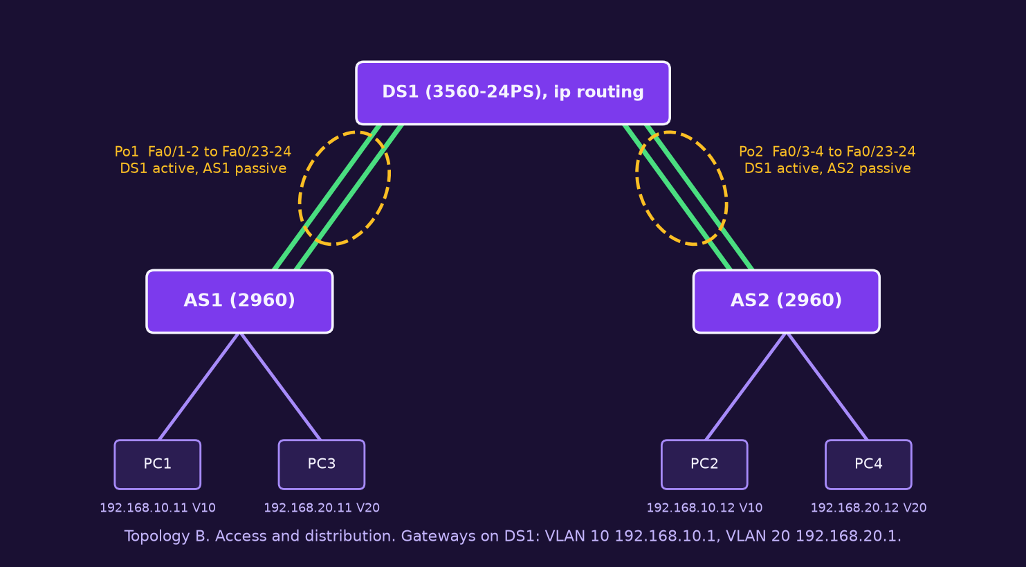
Here one distribution switch serves two access switches. DS1 is a 3560, so it needs one extra command on trunks: Layer 3 switches support both ISL and 802.1Q, so you must choose the encapsulation first. The 2960 only does 802.1Q and does not have that command.
DS1(config)# vlan 10
DS1(config-vlan)# vlan 20
DS1(config-vlan)# vlan 99
DS1(config-vlan)# exit
DS1(config)# port-channel load-balance src-dst-ip
DS1(config)# interface range FastEthernet0/1 - 2
DS1(config-if-range)# channel-group 1 mode active
DS1(config-if-range)# interface range FastEthernet0/3 - 4
DS1(config-if-range)# channel-group 2 mode active
DS1(config-if-range)# exit
DS1(config)# interface range Port-channel 1 - 2
DS1(config-if-range)# switchport trunk encapsulation dot1q
DS1(config-if-range)# switchport mode trunk
DS1(config-if-range)# switchport trunk native vlan 99
DS1(config-if-range)# switchport trunk allowed vlan 10,20,99
AS1(config)# interface range FastEthernet0/23 - 24
AS1(config-if-range)# channel-group 1 mode passive
AS1(config-if-range)# exit
AS1(config)# interface port-channel 1
AS1(config-if)# switchport mode trunk
AS1(config-if)# switchport trunk native vlan 99
AS1(config-if)# switchport trunk allowed vlan 10,20,99Repeat for AS2 with channel-group 1 on its own switch, because group numbers are local: AS2 uses Po1 even though DS1 calls that bundle Po2. Passive on the access side and active on DS1 is a valid pair. Then give DS1 its gateways:
DS1(config)# ip routing
DS1(config)# interface vlan 10
DS1(config-if)# ip address 192.168.10.1 255.255.255.0
DS1(config-if)# no shutdown
DS1(config-if)# interface vlan 20
DS1(config-if)# ip address 192.168.20.1 255.255.255.0
DS1(config-if)# no shutdown
ip routing turns the multilayer switch into a router, and each VLAN interface is the gateway for its subnet. Set the PC gateways to those addresses. Test PC1 to PC4 (different VLAN, different access switch) and PC1 to PC2 (same VLAN, across DS1). Verify with show etherchannel summary on DS1: you should see both Po1(SU) and Po2(SU). Shut one member in each bundle and confirm the PCs still reach each other.
Topology C: a Layer 3 EtherChannel
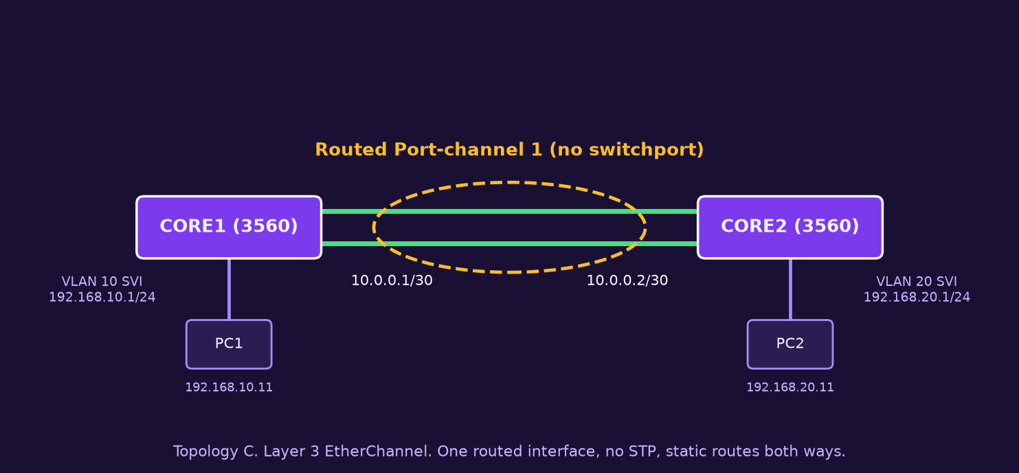
Between two multilayer switches you often do not want a trunk at all. A routed bundle gives one IP interface over several cables. Create the Port-channel first, make it routed, then add the members:
CORE1(config)# ip routing
CORE1(config)# interface port-channel 1
CORE1(config-if)# no switchport
CORE1(config-if)# ip address 10.0.0.1 255.255.255.252
CORE1(config-if)# exit
CORE1(config)# interface range FastEthernet0/1 - 2
CORE1(config-if-range)# no switchport
CORE1(config-if-range)# channel-group 1 mode active
CORE1(config-if-range)# exit
CORE1(config)# vlan 10
CORE1(config-vlan)# exit
CORE1(config)# interface vlan 10
CORE1(config-if)# ip address 192.168.10.1 255.255.255.0
CORE1(config-if)# exit
CORE1(config)# ip route 192.168.20.0 255.255.255.0 10.0.0.2
no switchport converts a port to Layer 3, and all members must be Layer 3 to join a routed bundle. CORE2 mirrors this with 10.0.0.2, its own VLAN 20 gateway, and ip route 192.168.10.0 255.255.255.0 10.0.0.1. Verify with show ip route, show etherchannel summary (look for Po1(RU), routed and in use) and a ping from PC1 to PC2. Two separate routed links with equal-cost routes also share load, but the bundle gives you one interface, one adjacency and one address, and the hash is the same.
Fault injection on Topology A
Rebuild Topology A with a working bundle, then break one thing at a time. For each fault, predict first, then read the output, fix it, and write a line in your report.
| Fault | How to cause it | What you should see |
|---|---|---|
| 1. Passive on both ends | channel-group 1 mode passive on both switches | Members stand-alone (I) or no Po1. STP blocks a link again |
| 2. Member differs | On SW2: interface Gi0/2 then switchport trunk native vlan 1 | Gi0/2 suspended (s) and a bundling error log message |
| 3. Allowed VLANs differ | On SW2 Po1: switchport trunk allowed vlan 10,99 | Members fail to bundle or are suspended |
| 4. Speed or duplex differs | On SW2 Gi0/2: speed 100 | Member cannot bundle with its partner |
| 5. LACP meets on | SW1 mode active, SW2 mode on | No bundle. Risk of a loop, which is why on is dangerous |
Diagnosis routine: show etherchannel summary for the flags, show etherchannel detail or show lacp neighbor for the partner, then compare show running-config interface Gi0/1 against Gi0/2 and against interface port-channel 1. Fix on the Port-channel where possible. Cisco's guidelines say the same: ports in a group must match, and changes to those parameters must be made on every port in the group. If a member stays broken, remove it with no channel-group and add it again. Whether Packet Tracer reproduces each message exactly is untested here, so describe what you observed.
Checkpoint
Where do you configure trunk settings on a bundle?
On the Port-channel interface, and members inherit them. Changing one member alone can get it suspended.
Why shut the members before building a bundle?
It prevents a temporary loop or mismatch while only one end is configured.
A bundle of two 1 Gbps links: can one file transfer reach 2 Gbps?
No. One flow hashes to one member, so it is limited to that member's speed.
What does the flag SU on Po1 mean?
S is Layer 2 and U is in use.
Design rules I follow
- Use LACP unless a device cannot speak it. Reserve
onfor gear that has nothing else, and document it. - Configure both ends the same way, then bring the members up together.
- Configure the Port-channel, not the members.
- Match speed, duplex, native VLAN and allowed VLANs before you add a port.
- Use two, four or eight members. Cisco notes that perfect balance needs those counts.
- Pick the hash for the traffic you have. Routed uplinks usually want IP-based hashing.
- Keep a spare cable and a spare port plan. A bundle with one member left is still a working link, but it is also a warning to fix.
- Remember what it does not protect: a failed switch, a failed line card, or a bad configuration pushed to both ends.
Checkpoint
Where is a Layer 3 EtherChannel different from a trunk bundle?
The members and the Port-channel are routed ports (no switchport) with an IP address, and there are no VLANs or STP on the link.
Why does DS1 use mode active and the access switches mode passive?
Active and passive is a valid pair. At least one end must start LACP, and active on the distribution side makes it the initiator.
What do you check first when a member shows s?
Compare its running configuration with the other members and with the Port-channel: speed, duplex, native VLAN, allowed VLANs.
Commands and flags
| Command | What it does |
|---|---|
channel-group N mode active|passive|on | Adds a port to group N with the chosen mode |
interface port-channel N | Enters the logical interface |
no channel-group | Removes a port from its group |
port-channel load-balance method | Sets the hash, global |
show etherchannel summary | One line per bundle with member flags |
show etherchannel detail | Per-member detail including partner |
show etherchannel load-balance | Shows the current hash method |
show lacp neighbor / internal | LACP partner and local port data |
show interfaces port-channel N | Status and combined bandwidth |
lacp system-priority N / lacp port-priority N | Tunes which ports are active (real IOS) |
| Flag | Meaning | Usual fix |
|---|---|---|
| P | Bundled in the port-channel | Nothing, this is correct |
| D | Port is down | Check cable and no shutdown |
| s | Suspended, settings do not match | Compare speed, duplex, native and allowed VLANs |
| I | Stand-alone, no partner bundled | Partner unconfigured, or passive meets passive |
| H | Hot-standby (LACP) | Normal if you configured more than 8 links |
| SU / SD (Po) | Layer 2 in use / down | SD means no member is bundled |
| RU (Po) | Routed, in use | Layer 3 bundle healthy |
Try-out project: a campus bundle (Topology D)
Now apply everything to a design of your own. The scenario is a fictional campus network modelled on a business school such as MUBS in Kampala. The names and addresses are invented and are not the real network of MUBS or any institution.
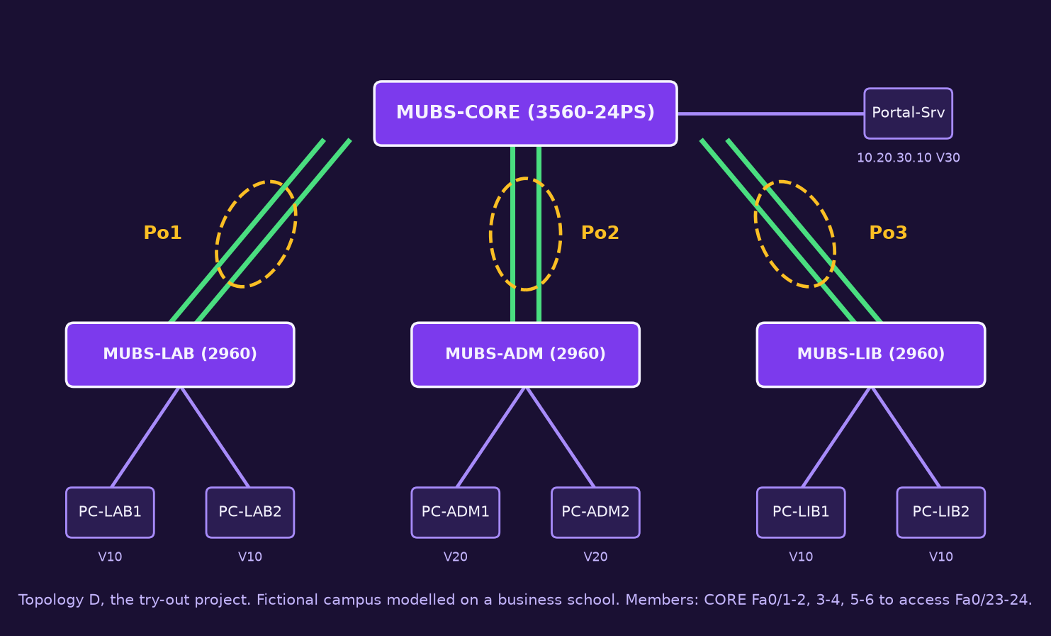
The brief: the lab, administration block and library each connect to the core with two FastEthernet cables. Management wants every uplink to survive a cable failure without wasting bandwidth, and wants staff, academic and server traffic kept in separate VLANs. Download the starter configuration, which holds the hostnames, VLANs, access ports, management addresses and the cabling and PC addressing tables. It deliberately leaves out the bundles, trunks and routing.
- Build Topology D in Packet Tracer with a 3560-24PS core and three 2960-24TT access switches. Apply the starter configuration.
- Bundle the three uplink pairs as LACP Port-channels 1, 2 and 3, active on the core, passive on the access side. Trunk with native VLAN 99 and allowed VLANs 10, 20, 30, 99 (remember
switchport trunk encapsulation dot1qon the core). - Route with
ip routingand SVIs on the core: VLAN 10 10.20.10.1, VLAN 20 10.20.20.1, VLAN 30 10.20.30.1, all /24. Set the PC and server gateways. - Balance traffic: choose a
port-channel load-balancemethod for the core and justify it in two sentences. - Prove it with
show etherchannel summaryon all four switches,show spanning-treeshowing no blocked uplink, and pings from every PC to the portal server. - Fail it: during a long ping from PC-LAB1 to Portal-Srv, shut one member of Po1. Record packets lost and Po1 state, then restore.
- Break it: cause and fix two faults from the fault table on any bundle. Show the output before and after.
- Recommend: in about 150 words, explain what still fails if MUBS-CORE dies, and what redundancy you would add.
Your submission
Do the project yourself, then tell me honestly what happened. Use the submit box below the article. You need to be signed in. You can upload up to 3 files (.pdf, .docx, .png, .jpg, .zip, .txt, .pkt, .pka, 20 MB each). A good pack is: your .pkt file, one PDF or DOCX report, and a ZIP of screenshots.
1. Report and reflection
- Evidence: the outputs from steps 5 to 7 with the device name visible.
- Predicted vs observed: what you expected in each fault and what appeared.
- Failover numbers: lost pings in Topology A step A4 and in project step 6, and what that tells you.
- What went wrong: one real mistake and how you found it.
- Design view: your recommendation from step 8, 250 to 400 words for the whole reflection.
2. Packet Tracer file
Save as Fullname_LACP_Project.pkt in its final working state with all three bundles up and routing working.
3. Critique two network engineers
Read the reflections other network engineers post in the comments and reply to at least two. Be specific: compare failover numbers, question a load balancing choice, and suggest one improvement. "Nice work" alone does not count.
How I will mark it
| Criterion | What I look for | Marks |
|---|---|---|
| Configuration (.pkt) | Three LACP bundles up, correct trunks and VLANs, routing works, load balancing set | 30 |
| Verification evidence | Correct show outputs from all four switches, read correctly | 15 |
| Failover test | Measured result with a sound explanation | 15 |
| Fault diagnosis | Two faults caused, found with show commands, fixed | 10 |
| Design recommendation | Clear on what still fails and a realistic fix | 10 |
| Reflection | Honest, specific, ties results to theory | 10 |
| Peer critique | At least two specific, constructive replies | 10 |
| Total | 100 |
Related: my posts on STP and RSTP and fixing an ACL that blocks your ping use the same predict, test, read, fix habit.
Sources and further reading
- Cisco: Configuring EtherChannels and Link-State Tracking, Catalyst 2960 Software Configuration Guide, IOS 15.0(2)SE
- Cisco: Configuring EtherChannels, Catalyst 2960 Software Configuration Guide, IOS 15.2(2)E
- Cisco: Understand EtherChannel Load Balance and Redundancy on Catalyst Switches
- IEEE 802.1AX-2020: Link Aggregation
- Cisco Packet Tracer help: supported protocols
- Cisco Networking Academy: download Packet Tracer