The first time I saw a broadcast storm in a real lab, someone had plugged a patch cable back into the same switch "to tidy up". Within seconds every port light was flashing like Christmas decorations and nobody could ping anything. That one cable taught the room more about Spanning Tree Protocol than any slide I could have shown. In this guide I want you to get that same lesson, but in Packet Tracer where breaking things costs nothing.
We will go through why loops happen, how STP picks a root bridge and decides which ports forward and which ones block, why classic STP is slow, and how RSTP fixes that. Then you will build the lab yourself, break it on purpose, time the recovery, and submit your work at the end. Take it one step at a time and keep Packet Tracer open beside this page.
What this guide covers
- Redundancy and the loop problem
- How STP works: BPDUs, Bridge ID and the root bridge
- Path cost, root ports and designated ports
- Port states, timers, PVST+ and RSTP
- PortFast, BPDU Guard and Root Guard
- The Packet Tracer lab, step by step
- Practice: try these
- Your lab submission
Why we build redundant paths, and why they bite
In any network that matters, one cable should not be able to take everyone offline. So we connect switches with more than one path. If the link between S1 and S2 fails, traffic can still go S1 to S3 to S2. That is redundancy, and it is what lets a network stay up 24/7/365.
The trouble is that Ethernet was never designed for loops. A router decrements the TTL in every IP packet, so a packet stuck in a routing loop eventually dies. An Ethernet frame has no TTL field at all. If a frame finds a loop between switches, it goes round and round until something physically breaks the loop. Three things go wrong at once:
- Broadcast storms. A switch floods a broadcast (an ARP request, for example) out of every port except the one it came in on. With a loop, every switch keeps flooding copies of copies. In seconds the links and the switch CPUs are saturated.
- MAC table instability. The same source MAC address arrives on one port, then a different port, then the first one again. The switch keeps rewriting its MAC address table and starts sending unicast frames the wrong way.
- Duplicate frames. A PC can receive the same frame two or more times, which confuses upper layer protocols.
Spanning Tree Protocol solves this by logically blocking just enough ports to leave one loop-free path between any two switches, while keeping the blocked links ready as backups. Cisco is very clear on this point: even when you think you have no physical redundancy, do not turn STP off, because one wrong patch cable can melt a bridged network in a fraction of a second.
How STP works
STP was standardised as IEEE 802.1D and is on by default on Cisco switches. The name says what it does. Spanning: it reaches every switch. Tree: one path to every branch, no loops. The whole process comes down to four steps:
- Switches exchange information in BPDUs.
- They elect one root bridge.
- Every other switch works out its best path to the root.
- Any port that is not part of a best path gets blocked.
BPDUs: how switches talk
A Bridge Protocol Data Unit (BPDU) is a small frame switches send to each other to run STP. The root sends one every 2 seconds, which is the hello timer. A BPDU carries the root bridge ID as the sender understands it, the sender's own bridge ID, the sender's cost to reach the root, the ID of the port it was sent from, and the STP timers. By comparing BPDUs, every switch can decide whether a neighbour has better information than it does.
The Bridge ID
Every switch has a Bridge ID (BID) of 8 bytes. The first 2 bytes are the priority field and the last 6 are the switch MAC address. On modern Cisco switches those 2 priority bytes are split into a 4-bit priority and a 12-bit extended system ID, which is simply the VLAN number. That is why the priority you see in show spanning-tree is never just 32768.
| Part | Size | Default value | Notes |
|---|---|---|---|
| Bridge priority | 4 bits | 32768 | Set in steps of 4096 (0, 4096, 8192 ... 61440) |
| Extended system ID | 12 bits | VLAN number | VLAN 1 adds 1, VLAN 10 adds 10 |
| MAC address | 6 bytes | Burned in | Tie-breaker when priorities are equal |
So for VLAN 1 the default priority shows as 32768 + 1 = 32769, and for VLAN 10 it shows as 32778. Lower is better.
Electing the root bridge
When the switches boot, each one claims to be root and sends BPDUs with its own BID in the root field. As soon as a switch hears a BPDU with a lower root BID than its own, it stops claiming and starts relaying the better one. After a few hellos, everyone agrees. The rule is simple: the lowest Bridge ID wins. Priority is compared first. If priorities tie, the lowest MAC address wins.
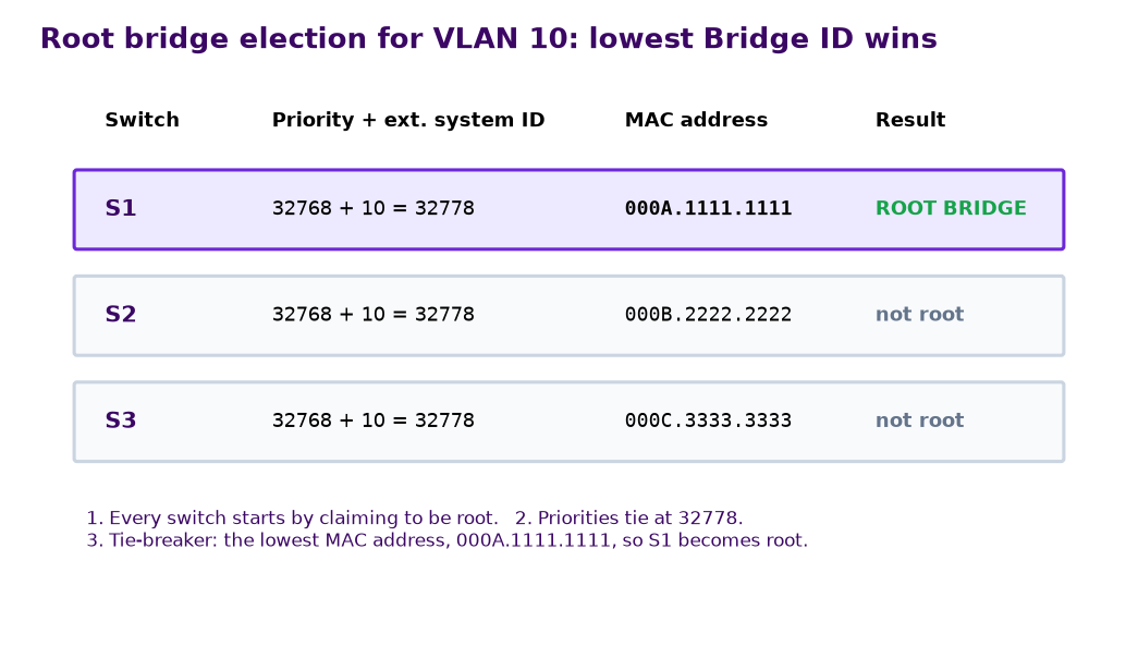
Notice that last point. Left alone, STP picks whichever switch happens to have the lowest MAC, which is often an old access switch in a cupboard. A good engineer chooses the root on purpose. We will do that in the lab.
Choosing the best path: cost, root ports and designated ports
Path cost
Each port has a cost based on its speed. Faster link, lower cost. The root path cost is the sum of the costs of the ports a BPDU enters on its way from the root. Cisco 2960 switches use the short (16-bit) method by default. There is also a long (32-bit) method from 802.1D-2004 that leaves room for faster links, enabled with spanning-tree pathcost method long.
| Link speed | Short cost (default) | Long cost |
|---|---|---|
| 10 Mbps | 100 | 2,000,000 |
| 100 Mbps (FastEthernet) | 19 | 200,000 |
| 1 Gbps (GigabitEthernet) | 4 | 20,000 |
| 10 Gbps | 2 | 2,000 |
In my three switch example with S1 as root, S3 can reach S1 directly over FastEthernet for a cost of 19, or through S2 for 19 + 19 = 38. The lowest total wins, so S3 uses the direct link.
Root ports
Every switch except the root has exactly one root port: the port with the best path to the root. When two ports look equally good, STP uses three tie-breakers in this order:
- Lowest root path cost.
- If equal, lowest Bridge ID of the neighbour sending the BPDU.
- If still equal, lowest port ID of the neighbour (port priority 128 plus the port number, shown as 128.2, 128.3 and so on).
Designated and non-designated ports
On every link (segment) one port is the designated port: the one sending the best BPDU onto that segment. All ports on the root bridge are designated, because nothing beats a cost of zero. Any port that ends up neither root nor designated is non-designated and blocks. RSTP gives these blocked ports more precise names: an alternate port is a backup path to the root through a different switch, and a backup port is a second connection to a segment the same switch already serves (you mostly see this with hubs).
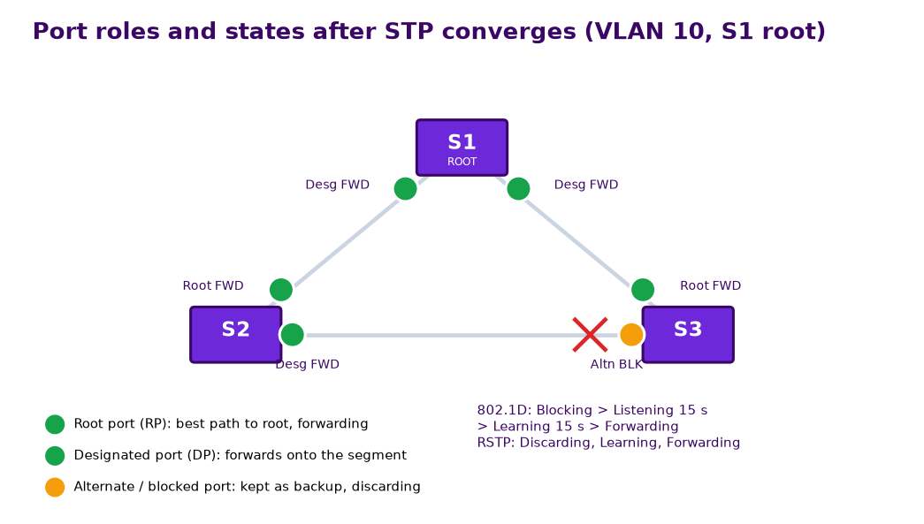
Look at the S2 to S3 link in Figure 2. Both switches have a cost of 19 to the root, so cost cannot decide. S2 has the lower Bridge ID, so S2 Fa0/2 becomes designated and S3 Fa0/2 blocks. One blocked port, and the loop is gone.
Port states, timers, PVST+ and RSTP
Classic 802.1D port states
A port does not jump straight from blocked to forwarding. If it did, it could open a temporary loop before the rest of the network caught up. Instead it walks through states:
| State | Receives BPDUs | Learns MACs | Forwards data | How long |
|---|---|---|---|---|
| Blocking | Yes | No | No | Until max age (20 s) expires or a better role is found |
| Listening | Yes (and sends) | No | No | Forward delay, 15 s |
| Learning | Yes | Yes | No | Forward delay, 15 s |
| Forwarding | Yes | Yes | Yes | Stable state |
| Disabled | No | No | No | Administratively down |
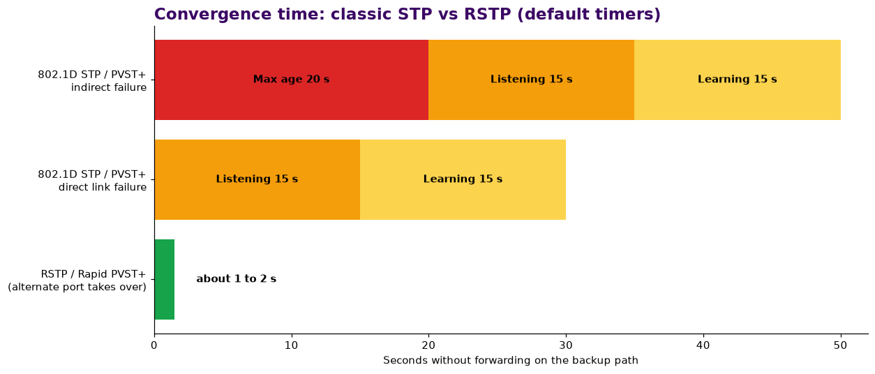
The three timers are worth memorising: hello 2 seconds, forward delay 15 seconds, max age 20 seconds. Add them up and you see the problem. If a switch loses its root port directly, the backup port spends 15 seconds listening and 15 learning, so about 30 seconds of outage. If the failure is somewhere else, the switch first waits up to 20 seconds of max age before it even notices, so about 50 seconds. In Packet Tracer you see this as an amber light that takes a long time to turn green.
PVST+: one tree per VLAN
The original 802.1D runs one tree for the whole network. Cisco's PVST+ (Per-VLAN Spanning Tree Plus) runs a separate instance for every VLAN, which is why the extended system ID exists. The big win is load balancing: you can make S1 the root for VLAN 10 and S2 the root for VLAN 20, so the link that blocks for one VLAN forwards for the other. Nothing sits idle. PVST+ is the default mode on Catalyst 2960 switches and in Packet Tracer.
RSTP and Rapid PVST+
Rapid Spanning Tree Protocol was published as IEEE 802.1w and later folded into 802.1D-2004. Cisco's per-VLAN version is Rapid PVST+. The election, Bridge ID and cost rules do not change at all. What changes is how fast it gets there:
- Fewer states. Disabled, blocking and listening merge into a single discarding state. You are left with discarding, learning and forwarding.
- Clearer roles. Root, designated, alternate and backup. The alternate port is already worked out, so when the root port fails it takes over almost immediately.
- Proposal and agreement. On point-to-point (full duplex) links, a designated port sends a proposal, the neighbour blocks its other non-edge ports (the sync), and replies with an agreement. The port then forwards at once, with no 30 second wait.
- Edge ports. Ports facing PCs, which Cisco configures with the PortFast keyword, go straight to forwarding and do not cause topology changes when they go up and down.
- BPDUs as keepalives. Every switch sends its own BPDU every hello. Miss three in a row and the neighbour is considered gone, so failure detection takes about 6 seconds instead of 20, and a physical link failure is detected straight away.
| Version | Standard | Trees | Convergence |
|---|---|---|---|
| STP | IEEE 802.1D | One for all VLANs | Slow (30 to 50 s) |
| PVST+ | Cisco | One per VLAN | Slow |
| RSTP | IEEE 802.1w | One for all VLANs | Fast |
| Rapid PVST+ | Cisco | One per VLAN | Fast |
| MSTP | IEEE 802.1s | Groups of VLANs | Fast |
PortFast, BPDU Guard and Root Guard
PortFast is for ports connected to PCs, printers and servers. The port skips listening and learning and forwards immediately, so a PC gets its DHCP address without a 30 second wait. Never use it on a link to another switch.
BPDU Guard protects PortFast ports. If a BPDU ever arrives on one, someone has plugged in a switch where a PC should be, so the port is shut down into the err-disabled state. I always pair the two.
Root Guard goes on ports facing switches that should never become root. If a superior BPDU arrives, the port is put into a root-inconsistent (blocked) state instead of handing over the root role. Loop Guard is its cousin: if BPDUs suddenly stop arriving on a blocked port, the port stays blocked instead of moving to forwarding, which protects you from one-way links.
Switch(config)# interface fa0/10
Switch(config-if)# spanning-tree portfast
Switch(config-if)# spanning-tree bpduguard enable
Switch(config)# interface fa0/1
Switch(config-if)# spanning-tree guard root
The Packet Tracer lab, step by step
You need Cisco Packet Tracer 8.x. Plan for about 90 minutes, and save a copy of your file before every step that breaks something. Your MAC addresses will be different from mine, so your root may be a different switch at first. That is part of the exercise.
Step 1: Build the topology
- Add three 2960 switches and name them S1, S2 and S3.
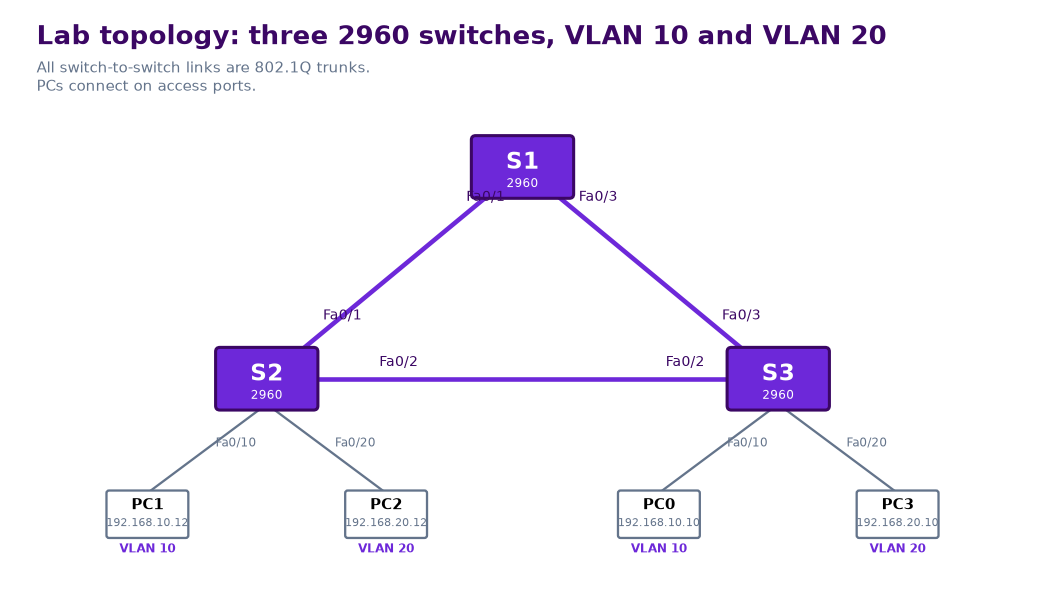
- Use copper straight-through cables: S1 Fa0/1 to S2 Fa0/1, S1 Fa0/3 to S3 Fa0/3, S2 Fa0/2 to S3 Fa0/2.
- Add four PCs. PC1 on S2 Fa0/10, PC2 on S2 Fa0/20, PC0 on S3 Fa0/10, PC3 on S3 Fa0/20.
- Addressing, mask 255.255.255.0 on all: PC1 192.168.10.12, PC0 192.168.10.10 (VLAN 10). PC2 192.168.20.12, PC3 192.168.20.10 (VLAN 20).
Step 2: VLANs and trunks
Create both VLANs on all three switches, including S1, which has no PCs. A switch only runs a spanning tree instance for a VLAN it knows about, so if you skip S1 your VLAN 10 and VLAN 20 trees will look strange.
S1(config)# hostname S1
S1(config)# vlan 10
S1(config-vlan)# name STAFF
S1(config-vlan)# vlan 20
S1(config-vlan)# name GUEST
S1(config-vlan)# exit
S1(config)# interface range fa0/1 - 3
S1(config-if-range)# switchport mode trunk
Repeat the VLANs and trunk commands on S2 and S3 (on those switches the trunks are Fa0/1 and Fa0/2 on S2, Fa0/2 and Fa0/3 on S3). Then put the PC ports in their VLANs, on S2 and S3:
S2(config)# interface fa0/10
S2(config-if)# switchport mode access
S2(config-if)# switchport access vlan 10
S2(config-if)# interface fa0/20
S2(config-if)# switchport mode access
S2(config-if)# switchport access vlan 20
Wait for the lights to settle. They start amber and turn green after about 30 seconds, and one switch port should stay amber. That is your blocked port. Ping PC0 to PC1 and PC3 to PC2. Both should work.
Step 3: Predict the root, then check it
Before you type anything else, run show version or show spanning-tree on each switch and write down each switch's MAC address. Predict which switch will be root for VLAN 10 and VLAN 20, and which port will block. Write your prediction down. You will need it for your reflection. Now check:
S3# show spanning-tree vlan 10Example output (your addresses and roles will differ):
VLAN0010
  Spanning tree enabled protocol ieee
  Root ID    Priority    32778
             Address     000A.1111.1111
             Cost        19
             Port        3(FastEthernet0/3)
             Hello Time  2 sec  Max Age 20 sec  Forward Delay 15 sec

  Bridge ID  Priority    32778  (priority 32768 sys-id-ext 10)
             Address     000C.3333.3333
             Hello Time  2 sec  Max Age 20 sec  Forward Delay 15 sec

Interface        Role Sts Cost      Prio.Nbr Type
---------------- ---- --- --------- -------- ----
Fa0/2            Altn BLK 19        128.2    P2p
Fa0/3            Root FWD 19        128.3    P2p
Fa0/10           Desg FWD 19        128.10   P2p
Read it from the top. "Spanning tree enabled protocol ieee" means PVST+. The Root ID block describes the root. The Bridge ID block describes this switch. If the two match, you will see "This bridge is the root". In the table, Altn BLK is the blocked port. Run the same command on all three switches for both VLANs and compare with your prediction.
Step 4: Choose the root bridge for each VLAN
Now we take control. I want S1 as root for VLAN 10 and S2 as root for VLAN 20, each backing up the other:
S1(config)# spanning-tree vlan 10 root primary
S1(config)# spanning-tree vlan 20 root secondary

S2(config)# spanning-tree vlan 20 root primary
S2(config)# spanning-tree vlan 10 root secondary
The root primary macro sets the priority to 24576, or 4096 below the current root if that is not low enough. root secondary sets 28672. You can also set a value directly, which I prefer in production because it is predictable:
S1(config)# spanning-tree vlan 10 priority 4096The priority must be a multiple of 4096, otherwise IOS rejects it. Check the result:
S2# show spanning-tree vlan 20Example output (trimmed):
VLAN0020
  Spanning tree enabled protocol ieee
  Root ID    Priority    24596
             Address     000B.2222.2222
             This bridge is the root
...
Interface        Role Sts Cost      Prio.Nbr Type
---------------- ---- --- --------- -------- ----
Fa0/1            Desg FWD 19        128.1    P2p
Fa0/2            Desg FWD 19        128.2    P2p
Fa0/20           Desg FWD 19        128.20   P2p
24596 is 24576 plus 20 for the VLAN. Now find the blocked port in each VLAN. For VLAN 10 it should be on the S2 to S3 link, and for VLAN 20 it should be on the S1 to S3 link. That is load balancing: each link carries traffic for at least one VLAN.
Step 5: Influence ports with cost
Priority decides the root. Cost decides the paths. On S3, make the direct link to S1 look expensive for VLAN 10 only:
S3(config)# interface fa0/3
S3(config-if)# spanning-tree vlan 10 cost 50
Through S2 the cost is now 19 + 19 = 38, which beats 50, so S3 Fa0/2 should become the root port for VLAN 10 and Fa0/3 should become Altn BLK. Confirm with show spanning-tree vlan 10, then undo it with no spanning-tree vlan 10 cost 50 so the rest of the lab matches.
Step 6: Break a link and time the convergence
- On PC0 open the Command Prompt and run
ping -t 192.168.10.12. Leave it running. - On S3, shut down the VLAN 10 root port:
interface fa0/3thenshutdown. Note the time on your phone. - Watch S3 Fa0/2 move through listening and learning to forwarding. Count the
Request timed outlines and time how long it takes for replies to come back. - Press Ctrl+C, then restore with
no shutdownon S3 Fa0/3.
With PVST+ you should lose about 30 seconds of pings, the two forward delays. Write your number down.
Step 7: Switch to Rapid PVST+ and compare
S1(config)# spanning-tree mode rapid-pvst
S2(config)# spanning-tree mode rapid-pvst
S3(config)# spanning-tree mode rapid-pvst
Run show spanning-tree vlan 10 again. The protocol line now reads "Spanning tree enabled protocol rstp". Repeat Step 6 exactly. This time you should lose somewhere between zero and two pings, because the alternate port was already chosen and takes over at once. This comparison is the heart of your reflection, so record both times honestly, even if Packet Tracer surprises you.
Step 8: PortFast and BPDU Guard, then trigger err-disable
On S2 and S3, protect the PC ports:
S2(config)# interface range fa0/10 , fa0/20
S2(config-if-range)# spanning-tree portfast
S2(config-if-range)# spanning-tree bpduguard enable
IOS warns you that PortFast should only be used on host ports. That warning is there for a reason. Unplug PC1 and plug it back in: the light should go green straight away instead of after 30 seconds.
Now play the careless technician. Add a fourth 2960 (S4) and connect it to S2 Fa0/10, in place of PC1. S4 sends BPDUs, and BPDU Guard reacts. Example output on S2:
%SPANTREE-2-BLOCK_BPDUGUARD: Received BPDU on port FastEthernet0/10 with BPDU Guard enabled. Disabling port.
%PM-4-ERR_DISABLE: bpduguard error detected on Fa0/10, putting Fa0/10 in err-disable state

S2# show interfaces status err-disabled
Port      Name    Status        Reason
Fa0/10            err-disabled  bpduguard
To recover, remove S4, reconnect PC1, and bounce the port:
S2(config)# interface fa0/10
S2(config-if)# shutdown
S2(config-if)# no shutdown
On real Catalyst switches you can also let the port recover by itself with errdisable recovery cause bpduguard and errdisable recovery interval 300. Packet Tracer support for that is limited, so do the manual recovery here. Finish with show spanning-tree summary and save the configs with copy running-config startup-config on every switch.
Commands we used
| Command | What it does |
|---|---|
show spanning-tree [vlan X] | Root, bridge ID, port roles and states |
spanning-tree vlan X root primary | secondary | Make this switch root or backup root |
spanning-tree vlan X priority N | Set priority directly (multiples of 4096) |
spanning-tree vlan X cost N | Change the port cost for one VLAN |
spanning-tree mode rapid-pvst | Switch to Rapid PVST+ |
spanning-tree portfast | Edge port, forward immediately |
spanning-tree bpduguard enable | Err-disable the port if a BPDU arrives |
spanning-tree guard root | Block superior BPDUs on this port |
Practice: try these
Work these out on paper before you open the answers. Use short (default) path costs unless I say otherwise.
- Bridge ID. A switch has the default priority and is running VLAN 20. What priority does
show spanning-tree vlan 20display? What would it display afterspanning-tree vlan 20 priority 8192? - Root election. In VLAN 10: SW-A has priority 32768 and MAC 00D0.BA11.2222. SW-B has priority 28672 and MAC 00E0.F900.0001. SW-C has priority 32768 and MAC 0001.4321.8765. Which switch is root? If SW-B is switched off, who takes over?
- Root primary. The current VLAN 30 root has priority 24576. You type
spanning-tree vlan 30 root primaryon another switch. What priority will it set? - Path cost. Four switches form a square. A is root. A to B is FastEthernet, B to D is GigabitEthernet, A to C is GigabitEthernet, C to D is GigabitEthernet. Find the root port of D and the root port of B. Which port blocks?
- Tie on the triangle. S1 is root. S2 (32769, 000B.2222.2222) and S3 (32769, 000C.3333.3333) both have a cost of 19 to the root and connect to each other on Fa0/2. Which port blocks, and why?
- RSTP roles. S3 is designated for a hub segment and is connected to that hub on both Fa0/23 and Fa0/24. Name the RSTP role of each port.
- Timers. With classic STP and default timers, how long can it take a blocked port to forward after an indirect failure? After a direct failure of the root port?
Show the answers
- 32768 + 20 = 32788. After the change it shows 8192 + 20 = 8212.
- SW-B wins on priority (28672 + 10 = 28682 beats 32778); MAC addresses are not even compared. Without SW-B, A and C tie on 32778, so the lowest MAC wins: SW-C (0001.4321.8765).
- 24576 is not low enough to beat a tie, so the macro goes 4096 lower: 20480.
- D: via C = 4 + 4 = 8, via B = 19 + 4 = 23, so D's root port faces C. B: direct = 19, via D and C = 4 + 4 + 4 = 12, so B's root port faces D, not A. On the A to B link A's port is designated (root), and B's port is neither root nor designated, so B's port toward A blocks. Surprised? That is why cost matters more than "nearest switch".
- Cost ties at 19, so the lower Bridge ID owns the segment. S2 (000B...) beats S3 (000C...), so S2 Fa0/2 is designated and S3 Fa0/2 blocks (Altn BLK).
- Both ports hear S3's own BPDUs. The lower port ID wins: Fa0/23 is designated (128.23) and Fa0/24 is a backup port.
- Indirect: 20 s max age + 15 s listening + 15 s learning = about 50 s. Direct: 15 + 15 = about 30 s. RSTP brings both down to about 1 to 2 seconds.
Your lab submission
This is where the learning sticks. Do the lab yourself, then tell me honestly what happened. Your submission has three parts.
1. Write your reflection
Answer these in your own words, 250 to 400 words in total:
- Predicted vs observed: which switch did you predict as root and which port did you expect to block? Were you right? If not, why?
- Convergence: how many seconds (or lost pings) did PVST+ take in Step 6, and how many did Rapid PVST+ take in Step 7? Explain the difference using roles and states.
- What broke: what went wrong during the lab, and how did you fix it? A forgotten VLAN on S1 counts.
- What you learnt: one thing you would now do differently on a real network.
2. Submit your Packet Tracer file
Save your finished lab as Fullname_STP_Lab.pkt, for example Ssendi_Samuel_STP_Lab.pkt. It should include the final state after Step 8, with Rapid PVST+, the root configuration and PortFast with BPDU Guard on all PC ports. Upload it together with your reflection using the Submit your lab box below on this page. You need to be signed in.
3. Critique two network engineers
Read the reflections other network engineers have posted in the comments and reply to at least two. A good critique is specific. Compare their convergence times with yours, point out anything in their reasoning that does not match the theory, and suggest one improvement. "Nice work" alone does not count.
How I will mark it
| Criterion | What I look for | Marks |
|---|---|---|
| Lab configuration (.pkt) | Correct topology, VLANs and trunks, root per VLAN, Rapid PVST+, PortFast and BPDU Guard on PC ports only | 35 |
| Verification and analysis | Correct reading of show spanning-tree, root and blocked ports explained | 20 |
| Convergence comparison | Measured PVST+ and Rapid PVST+ times with a clear explanation | 15 |
| Reflection | Honest prediction vs result, what broke, what you learnt | 15 |
| Peer critique | At least two specific, constructive replies | 15 |
| Total | 100 |
If you are new to Packet Tracer troubleshooting, my post on fixing an ACL that blocks your ping uses the same habits: predict, test, read the output, then fix.