Packet Tracer – Basic VLAN Configuration Answers
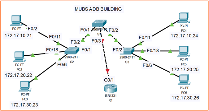
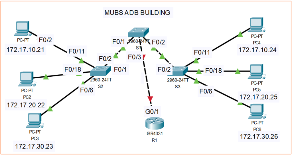
Topology
Addressing Table
| Device | Interface | IP Address | Subnet Mask | Default Gateway |
|---|---|---|---|---|
| S1 | VLAN 99 | 172.17.99.11 | 255.255.255.0 | N/A |
| S2 | VLAN 99 | 172.17.99.12 | 255.255.255.0 | N/A |
| S3 | VLAN 99 | 172.17.99.13 | 255.255.255.0 | N/A |
| PC1 | NIC | 172.17.10.21 | 255.255.255.0 | 172.17.10.1 |
| PC2 | NIC | 172.17.20.22 | 255.255.255.0 | 172.17.20.1 |
| PC3 | NIC | 172.17.30.23 | 255.255.255.0 | 172.17.30.1 |
| PC4 | NIC | 172.17.10.24 | 255.255.255.0 | 172.17.10.1 |
| PC5 | NIC | 172.17.20.25 | 255.255.255.0 | 172.17.20.1 |
| PC6 | NIC | 172.17.30.26 | 255.255.255.0 | 172.17.30.1 |
Port Assignments (Switches 2 and 3)
| Ports | Assignment | Network |
|---|---|---|
| Fa0/1-0/5 | VLAN 99 – Management&Native | 172.17.99.0 /24 |
| Fa06-0/10 | VLAN 30 – Guest(Default) | 172.17.30.0 /24 |
| Fa0/11 – 0/17 | VLAN 10 – Faculty/Staff | 172.17.10.0 /24 |
| Fa0/18 – 0/24 | VLAN 20 – Students | 172.17.20.0 /24 |
Router Interface Assignments (R1 – Router-on-a-Stick)
| Interface | Assignment (dot1Q 10) | IP Address / Subnet Mask | Description |
| G0/1.10 | VLAN 10 – Faculty / Staff | 172.17.10.1 /24 | VLAN 10 Default gateway |
| G0/1.20 | VLAN 20 – Students | 172.17.20.1 /24 | VLAN 20 Default gateway |
| G0/1.30 | VLAN 30 – Guest | 172.17.30.1 /24 | VLAN 30 Default gateway |
| G0/1.99 | VLAN 99 – Management & Native | 172.17.99.1 /24 | VLAN 99 Default gateway |
| G0/1 | Physical trunk interface to Switch S1 | – | Carries VLANs 10, 20, 30, 99 |
Learning Objectives
Perform basic configuration tasks on a switch
- Create VLANs
- Assign switch ports to a VLAN
- Add, move, and change ports
- Verify VLAN configuration
- Enable trunking on inter-switch connections
- Verify trunk configuration
- Save the VLAN configuration
REQUIRED:
You have been contracted by the Makerere University Business School IT Department to implement the VLAN configuration for the new network in the ADB Building. Using Cisco Packet Tracer and your knowledge from the Routing and Switching course, perform the following tasks:
Task 1: Perform Basic Switch Configurations
Perform Basic Switch Configurations. Packet Tracer will only grade switch hostnames.
- Configure the switch hostnames.
- Disable DNS lookup.
- Configure an EXEC mode password of “samuel”.
- Configure a password of “ssentumbwe” for console connections.
- Configure a password of “tana” for vty connections.
Solution: Build the Network and Configure Basic Device Settings
In this part of the lab you have already drawn or powered on the topology. The next step is to configure basic settings on the switches and routers so that they have clear identities and are protected by passwords.
The goal is that by the end of this section you will understand what each command means and why you are typing it, not just copy and paste it.
1. Configure the switch and router hostnames
By default, Cisco devices use generic names such as Switch or Router. Setting a hostname helps you to identify each device in the network and also makes your command line prompt more meaningful.
On the switch:
Switch> enable
Switch# configure terminal
Switch(config)# hostname S1
S1(config)#
On the router:
Router> enable
Router# configure terminal
Router(config)# hostname R1
R1(config)#
Explanation of the commands
Switch> and Router>
This is user EXEC mode. You can run only basic monitoring commands here.
enable
Moves you from user EXEC mode to privileged EXEC mode, indicated by the # prompt.
Privileged EXEC mode (Switch#, Router#) allows you to run powerful commands such as show running-config, copy, and enter configuration mode.
configure terminal (often written as conf t)
Takes you from privileged EXEC mode into global configuration mode, indicated by (config)#.
In this mode you can make permanent changes to the device configuration.
hostname S1, SW2, SW3 and hostname R1
Sets the hostname of the device. This is the name that appears in the prompt.
After you press Enter, the prompt changes to S1(config)# or R1(config)#, which confirms that the new name has been applied.
Use meaningful hostnames that match your topology diagram. For example, S1, S2 for switches and R1, R2 for routers.
2. Disable DNS lookup
When you mistype a command, the device may try to resolve the word as a hostname using DNS. In a lab environment this causes an annoying delay. We disable that behaviour.
On each device (switch and router), in global configuration mode:
S1(config)# no ip domain-lookup
R1(config)# no ip domain-lookup
Explanation
no ip domain-lookup
Disables the automatic DNS lookup on the device.
If you accidentally type a wrong command such as switc instead of switch, the device will immediately return an error instead of trying to find a host called switc somewhere on the network.
This command is not mandatory in production environments, but it is very helpful in labs and training.
3. Configure an EXEC mode password of samuel
The enable password protects access to privileged EXEC mode. Anyone who wants to run powerful commands must first enter this password after typing enable.
On each device:
S1(config)# enable secret samuel
R1(config)# enable secret samuel
Explanation
enable secret samuel
Sets the encrypted enable password to samuel.
There are two similar commands:
enable password
Stores the password in plain text in the configuration. This is not secure.enable secret
Stores the password in an encrypted form (by default, one way MD5). It is more secure and overridesenable passwordif both are set.
In modern configurations you should always use enable secret, not enable password.
Usage in practice:
- At the
Switch>orRouter>prompt, type:enable - The device prompts for a password.
- You type:
samuel - If correct, you enter privileged EXEC mode (
S1#orR1#).
4. Configure a console password of ssentumbwe
The console line controls physical access using the console cable. Anyone who plugs a console cable into the device should be challenged for a password.
On each device, in global configuration mode:
S1(config)# line console 0
S1(config-line)# password ssentumbwe
S1(config-line)# login
S1(config-line)# exit
You would repeat the same logic on the router:
R1(config)# line console 0
R1(config-line)# password ssentumbwe
R1(config-line)# login
R1(config-line)# exit
Explanation of the line commands
line
This command enters line configuration mode. In Cisco IOS, a line is a type of access into the device. Common line types are:
consolefor physical console accessvtyfor virtual terminal access (Telnet or SSH)auxfor the auxiliary port (often used with modems)
line console 0
Selects console line 0 and enters line configuration mode, indicated by the prompt (config-line)#.
Why 0?
There is typically only one console line, numbered 0. You must specify the number even if there is only one.
password ssentumbwe
Sets the password for that line. Anyone using the console must provide this password.
login
Tells the device to prompt for a password on this line and to use the password configured with the password command.
If you forget login, the password will not actually be required.
exit
Leaves line configuration mode and returns to global configuration mode.
After this configuration, when someone connects to the console port, they will be prompted for a password. They must type ssentumbwe before they can access user EXEC mode.
5. Configure a password of tana for VTY (Telnet/SSH) connections
VTY lines are logical lines used for remote access via Telnet or SSH. These lines allow you to manage the device over the network instead of physically standing next to it.
On each device, in global configuration mode:
S1(config)# line vty 0 15
S1(config-line)# password tana
S1(config-line)# login
S1(config-line)# exit
You would repeat the same commands on the router:
R1(config)# line vty 0 15
R1(config-line)# password tana
R1(config-line)# login
R1(config-line)# exit
Explanation of VTY and the numbering
line vty 0 15
Enters line configuration mode for VTY lines 0 to 15.
Terminology:
- VTY stands for Virtual Teletype. These are virtual lines used for remote sessions (Telnet and SSH).
- The numbers
0 15mean you are selecting a range of lines from0up to15. That is 16 lines in total:0, 1, 2, ..., 15.
Different devices may have:
line vty 0 4(5 lines) on smaller or older devicesline vty 0 15(16 lines) on many modern devices- On some high end devices, even higher ranges are supported.
Why select a range?
Because each remote session uses one line. If you configure only line vty 0 and another user connects on vty 1, they might bypass your password. Configuring 0 15 ensures all VTY lines share the same security settings.
password tana
Sets the password tana for all selected VTY lines. Any Telnet or SSH session that reaches these lines will require that password.
login
As with the console, instructs the device to prompt for and check the VTY password when someone connects.
exit
Leaves line configuration mode.
Note: In a real secure network, you normally also specify that only SSH is allowed and configure user accounts, for example:
transport input sshandlogin local.
For this basic lab, the requirement is only to set a VTY password.
After this configuration, when you connect remotely to the device using Telnet or SSH, you will see a password prompt. You must enter tana to gain access to user EXEC mode. You will then use enable and the samuel password to reach privileged EXEC mode.
6. Save the configuration
If you do not save your configuration, it will be lost when the device reloads. To save:
S1# write memory
or
S1# copy running-config startup-config
Destination filename [startup-config]?  <Press Enter>
Do the same on the router:
R1# write memory
Explanation
running-config
The configuration currently active in RAM. Changes you make with configure terminal are applied to the running configuration immediately.
startup-config
The configuration stored in NVRAM that the device loads when it boots.
write memory
Legacy shortcut that copies the running configuration to the startup configuration.
copy running-config startup-config
Explicitly copies the running configuration into the startup configuration file. After this, your settings are preserved across reloads.
7. Verification
To check your work at any time:
S1# show running-config
R1# show running-config
Explanation
show running-config
Displays the current configuration in RAM.
You should be able to see:
hostname S1orhostname R1no ip domain-lookupenable secret samuel- The console line section with
password ssentumbweandlogin - The VTY line section with
password tanaandlogin
Encourage your students to read the configuration output and match it back to the commands they entered. That way they will understand how each part of the configuration file relates to the commands they typed, instead of just memorising sequences.
Summary of the basic configuration commands
This short summary helps you quickly remember what each command does and where it is used.
Modes
enable
Moves from user EXEC mode (>) to privileged EXEC mode (#).configure terminal
Enters global configuration mode(config)#where you can change the device configuration.
Hostname
hostname S1
hostname R1
Sets the device name that appears in the CLI prompt and in the configuration. Used in global configuration mode.
Disable DNS lookup
no ip domain-lookup
Disables DNS lookup so the device does not try to resolve mistyped commands as hostnames.
Enable (privileged EXEC) password
enable secret samuel
Configures the encrypted password required to enter privileged EXEC mode. Preferred over enable password.
Console line password
line console 0
 password ssentumbwe
 login
Configures the physical console access.
line console 0selects the console linepassword ssentumbwesets the line passwordlogintells the device to request this password
VTY (Telnet/SSH) line password
line vty 0 15
 password tana
 login
Configures all virtual terminal lines (0 to 15) used for remote access. The same password and login structure is used as for the console.
Save the configuration
write memory
or
copy running-config startup-config
Copies the running configuration to startup configuration so it is preserved after reload.
Reusing the configuration on multiple devices (to save time)
In many labs you have several devices such as S1, S2, S3 and R1. Apart from the hostname and interface settings, the basic security configuration is usually the same on all devices. Instead of typing every command manually on each device, you can prepare a small template and reuse it.
1. Create a base configuration template
In a text editor on your computer, create a block like this:
configure terminal

hostname S1
no ip domain-lookup
enable secret samuel

line console 0
 password ssentumbwe
 login

line vty 0 15
 password tana
 login

end
write memory
Explanation:
configure terminalputs the device into global configuration modehostnamesets the device nameno ip domain-lookupdisables DNS lookupenable secretsets the encrypted enable passwordline console 0andline vty 0 15sections set console and remote access passwordsendreturns to privileged EXEC modewrite memorysaves the configuration
You will use this same block on all switches and routers, only changing the hostname each time.
2. Apply the template to the first switch (S1)
- Connect to S1 and type:
enable - Paste the entire block into the console.
- The device will execute each command and end with a saved configuration.
- Your prompt should show
S1#and the settings will be in place.
3. Reuse the same template on S2 and S3
For S2, change only the hostname line in your text editor:
hostname S2
Then copy and paste the modified block on S2 (after typing enable).
For S3, do the same:
hostname S3
Paste on S3.
This way, all switches share the same security configuration and behaviour, but each has a unique hostname.
4. Use a similar template for the router (R1)
For the router, you can use the same structure with hostname R1:
configure terminal

hostname R1
no ip domain-lookup
enable secret samuel

line console 0
 password ssentumbwe
 login

line vty 0 15
 password tana
 login

end
write memory
Paste this on R1 after typing enable.
Later, you can add router specific interface and routing commands.
5. Copy from the running configuration when needed
Another useful approach is to configure one device fully, then copy parts of its running configuration.
On S1:
S1# show running-config
Scroll to the sections you want to reuse, such as:
hostname S1
no ip domain-lookup
enable secret 5 <encrypted-password>

line console 0
 password ssentumbwe
 login

line vty 0 15
 password tana
 login
Copy this block into a text editor, change hostname S1 to hostname S2, and paste it onto S2 (after typing enable).
Task 2: Configure and Activate Ethernet Interfaces
Configure the Ethernet interfaces of the six PCs with the IP addresses and default gateways from the addressing table.
Note: The IP address for PC1 will be marked as wrong for now. You will change the PC1 IP address later.
Task 3: Configure VLANs on the Switch
Step 1. Create VLANs on switch S1.
Use the vlan vlan-id command in global configuration mode to add VLANs to switch S1. There are four VLANs to configure for this activity. After you create the VLAN, you will be in vlan configuration mode, where you can assign a name to the VLAN with the vlan name command.
S1(config)#vlan 99
S1(config-vlan)#name Management&Native
S1(config-vlan)#exit
S1(config)#vlan 10
S1(config-vlan)#name Faculty/Staff
S1(config-vlan)#exit
S1(config)#vlan 20
S1(config-vlan)#name Students
S1(config-vlan)#exit
S1(config)#vlan 30
S1(config-vlan)#name Guest(Default)
S1(config-vlan)#exit
Step 2. Verify that the VLANs have been created on S1.
Use the show vlan brief command to verify that the VLANs have been created.
S1#show vlan brief
VLAN Name                             Status    Ports
---- -------------------------------- --------- -------------------------------
1    default                          active    Fa0/1, Fa0/2, Fa0/4, Fa0/5
                                                Fa0/6, Fa0/7, Fa0/8, Fa0/9
                                                Fa0/10, Fa0/11, Fa0/12, Fa0/13
                                                Fa0/14, Fa0/15, Fa0/16, Fa0/17
                                                Fa0/18, Fa0/19, Fa0/20, Fa0/21
                                                Fa0/22, Fa0/23, Fa0/24, Gi0/1
                                                Gi0/2
10   Faculty/Staff                    active
20   Students                         active
30   Guest(Default)                   active
99   Management&Native                active
Step 3. Configure and name VLANs on switches S2 and S3.
Create and name VLANs 10, 20, 30, and 99 on S2 and S3 using the commands from Step 1. Verify the correct configuration with the show vlan brief command.
What ports are currently assigned to the four VLANs you have created?
none
Step 4. Assign switch ports to VLANs on S2 and S3.
Refer to the port assignment table on page 1. Ports are assigned to VLANs in interface configuration mode, using the switchport access vlan vlan-id command. Packet Tracer will only grade the first interface in each range (the interface the PC is connected to). Normally you would use the interface range command, but Packet Tracer does not support this command.
S2(config)#interface fastEthernet0/6
S2(config-if)#switchport access vlan 30
S2(config-if)#interface fastEthernet0/11
S2(config-if)#switchport access vlan 10
S2(config-if)#interface fastEthernet0/18
S2(config-if)#switchport access vlan 20
S2(config-if)#end
S2#copy running-config startup-config
Destination filename [startup-config]? [enter]
Building configuration...
[OK]
Note: The Fa0/11 access VLAN will be marked as wrong for now. You will correct this later in the activity.
Repeat the same commands on S3.
Step 5. Determine which ports have been added.
Use the show vlan id vlan-number command on S2 to see which ports are assigned to VLAN 10.
Which ports are assigned to VLAN 10?
Fa0/11, Fa0/12, Fa0/13, Fa0/14, Fa0/15, Fa0/16, Fa0/17
Note: The show vlan name vlan-name displays the same output.
You can also view VLAN assignment information using the show interfaces switchport command.
Step 6. Assign the management VLAN.
A management VLAN is any VLAN that you configure to access the management capabilities of a switch. VLAN 1 serves as the management VLAN if you did not specifically define another VLAN. You assign the management VLAN an IP address and subnet mask. A switch can be managed via HTTP, Telnet, SSH, or SNMP. Because the out-of-the-box configuration of a Cisco switch has VLAN 1 as the default VLAN, VLAN 1 is a bad choice as the management VLAN. You do not want an arbitrary user who is connecting to a switch to default to the management VLAN. Recall that you configured the management VLAN as VLAN 99 earlier in this lab.
From interface configuration mode, use the ip address command to assign the management IP address to the switches.
S1(config)#interface vlan 99
S1(config-if)#ip address 172.17.99.11 255.255.255.0
S1(config-if)#no shutdown

S2(config)#interface vlan 99
S2(config-if)#ip address 172.17.99.12 255.255.255.0
S2(config-if)#no shutdown

S3(config)#interface vlan 99
S3(config-if)#ip address 172.17.99.13 255.255.255.0
S3(config-if)#no shutdown
Assigning a management address allows IP communication between the switches, and also allows any host connected to a port assigned to VLAN 99 to connect to the switches. Because VLAN 99 is configured as the management VLAN, any ports assigned to this VLAN are considered management ports and should be secured to control which devices can connect to these ports.
Step 7. Configure trunking and the native VLAN for the trunking ports on all switches.
Trunks are connections between the switches that allow the switches to exchange information for all VLANS. By default, a trunk port belongs to all VLANs, as opposed to an access port, which can only belong to a single VLAN. If the switch supports both ISL and 802.1Q VLAN encapsulation, the trunks must specify which method is being used. Because the 2960 switch only supports 802.1Q trunking, it is not specified in this activity.
A native VLAN is assigned to an 802.1Q trunk port. In the topology, the native VLAN is VLAN 99. An 802.1Q trunk port supports traffic coming from many VLANs (tagged traffic) as well as traffic that does not come from a VLAN (untagged traffic). The 802.1Q trunk port places untagged traffic on the native VLAN. Untagged traffic is generated by a computer attached to a switch port that is configured with the native VLAN. One of the IEEE 802.1Q specifications for Native VLANs is to maintain backward compatibility with untagged traffic common to legacy LAN scenarios. For the purposes of this activity, a native VLAN serves as a common identifier on opposing ends of a trunk link. It is a best practice to use a VLAN other than VLAN 1 as the native VLAN.
S1(config)#interface fa0/1
S1(config-if)#switchport mode trunk
S1(config-if)#switchport trunk native vlan 99
S1(config-if)#interface fa0/2
S1(config-if)#switchport mode trunk
S1(config-if)#switchport trunk native vlan 99
S1(config-if)#end
S1(config)# interface fastEthernet0/3
S1(config-if)# switchport mode trunk
S1(config-if)# switchport trunk native vlan 99


S2(config)#interface fa0/1
S2(config-if)#switchport mode trunk
S2(config-if)#switchport trunk native vlan 99
S2(config-if)#end

S3(config)#interface fa0/2
S3(config-if)#switchport mode trunk
S3(config-if)#switchport trunk native vlan 99
S3(config-if)#end
Verify that the trunks have been configured with the show interface trunk command.
S1#show interface trunk
Port        Mode         Encapsulation  Status        Native vlan
Fa0/1       on           802.1q         trunking      99
Fa0/2       on           802.1q         trunking      99

Port        Vlans allowed on trunk
Fa0/1       1-1005
Fa0/2       1-1005

Port        Vlans allowed and active in management domain
Fa0/1       1,10,20,30,99,1002,1003,1004,1005
Fa0/2       1,10,20,30,99,1002,1003,1004,1005

Port        Vlans in spanning tree forwarding state and not pruned
Fa0/1       1,10,20,30,99,1002,1003,1004,1005
Fa0/2       1,10,20,30,99,1002,1003,1004,1005
Step 8. Verify that the switches can communicate.
From S1, ping the management address on both S2 and S3.
S1#ping 172.17.99.12
Type escape sequence to abort.
Sending 5, 100-byte ICMP Echos to 172.17.99.12, timeout is 2 seconds:
..!!!
Success rate is 100 percent (5/5), round-trip min/avg/max = 1/2/9 ms

S1#ping 172.17.99.13
Type escape sequence to abort.
Sending 5, 100-byte ICMP Echos to 172.17.99.13, timeout is 2 seconds:
..!!!
Success rate is 80 percent (4/5), round-trip min/avg/max = 1/1/1 ms
Step 9. Ping several hosts from PC2.
Ping from host PC2 to host PC1 (172.17.10.21). Is the ping attempt successful?
no
Ping from host PC2 to the switch VLAN 99 IP address 172.17.99.12. Is the ping attempt successful?
no
Because these hosts are on different subnets and in different VLANS, they cannot communicate without a Layer 3 device to route between the separate subnetworks.
Ping from host PC2 to host PC5. Is the ping attempt successful?
yes
Because PC2 is in the same VLAN and the same subnet as PC5, the ping is successful.
Step 10. Move PC1 into the same VLAN as PC2.
The port connected to PC2 (S2 Fa0/18) is assigned to VLAN 20, and the port connected to PC1 (S2 Fa0/11) is assigned to VLAN 10. Reassign the S2 Fa0/11 port to VLAN 20. You do not need to first remove a port from a VLAN to change its VLAN membership. After you reassign a port to a new VLAN, that port is automatically removed from its previous VLAN.
S2#configure terminal
Enter configuration commands, one per line. End with CNTL/Z.
S2(config)#interface fastethernet 0/11
S2(config-if)#switchport access vlan 20
S2(config-if)#end
Ping from host PC2 to host PC1. Is the ping attempt successful?
no
Step 11. Change the IP address and network on PC1.
Change the IP address on PC1 to 172.17.20.21. The subnet mask and default gateway can remain the same. Once again, ping from host PC2 to host PC1, using the newly assigned IP address.
Is the ping attempt successful?
yes
Why was this attempt successful?
Hosts must be in the same VLAN and in the same subnet to communicate directly through the switches.
Final Switch Configurations
S1
hostname S1
!
enable secret samuel
no ip domain-lookup
!
interface FastEthernet0/1
switchport trunk native vlan 99
switchport mode trunk
!
interface FastEthernet0/2
switchport trunk native vlan 99
switchport mode trunk
!
interface FastEthernet0/3
switchport trunk native vlan 99
switchport mode trunk
!
interface FastEthernet0/4
switchport trunk native vlan 99
switchport mode trunk
!
interface FastEthernet0/5
switchport trunk native vlan 99
switchport mode trunk
!
interface FastEthernet0/6
shutdown
!
<all remaining FastEthernet and GigabitEthernet interface are shutdown>
!
interface Vlan1
no ip address
no ip route-cache
!
interface Vlan99
ip address 172.17.99.11 255.255.255.0
no ip route-cache
!
line con 0
exec-timeout 0 0
password samuel
logging synchronous
login
line vty 0 4
exec-timeout 0 0
password ssentumbwe
logging synchronous
login
line vty 5 15
exec-timeout 0 0
password tana
logging synchronous
login
!
end
S2
hostname S2
!
enable secret samuel
no ip domain-lookup
!
interface FastEthernet0/1
switchport trunk native vlan 99
switchport mode trunk
!
interface FastEthernet0/2
switchport trunk native vlan 99
switchport mode trunk
!
interface FastEthernet0/3
switchport trunk native vlan 99
switchport mode trunk
!
interface FastEthernet0/4
switchport trunk native vlan 99
switchport mode trunk
!
interface FastEthernet0/5
switchport trunk native vlan 99
switchport mode trunk
!
interface FastEthernet0/6
switchport access vlan 30
switchport mode access
!
interface FastEthernet0/7
switchport access vlan 30
switchport mode access
shutdown
!
interface FastEthernet0/8
switchport access vlan 30
switchport mode access
shutdown
!
interface FastEthernet0/9
switchport access vlan 30
switchport mode access
shutdown
!
interface FastEthernet0/10
switchport access vlan 30
switchport mode access
shutdown
!
interface FastEthernet0/11
switchport access vlan 20
switchport mode access
!
interface FastEthernet0/12
switchport access vlan 10
switchport mode access
shutdown
!
interface FastEthernet0/13
switchport access vlan 10
switchport mode access
shutdown
!
interface FastEthernet0/14
switchport access vlan 10
switchport mode access
shutdown
!
interface FastEthernet0/15
switchport access vlan 10
switchport mode access
shutdown
!
interface FastEthernet0/16
switchport access vlan 10
switchport mode access
shutdown
!
interface FastEthernet0/17
switchport access vlan 10
switchport mode access
shutdown
!
interface FastEthernet0/18
switchport access vlan 20
switchport mode access
!
interface FastEthernet0/19
switchport access vlan 20
switchport mode access
shutdown
!
interface FastEthernet0/20
switchport access vlan 20
switchport mode access
shutdown
!
interface FastEthernet0/21
switchport access vlan 20
switchport mode access
shutdown
!
interface FastEthernet0/22
switchport access vlan 20
switchport mode access
shutdown
!
interface FastEthernet0/23
switchport access vlan 20
switchport mode access
shutdown
!
interface FastEthernet0/24
switchport access vlan 20
switchport mode access
shutdown
!
interface GigabitEthernet0/1
shutdown
!
interface GigabitEthernet0/2
shutdown
!
interface Vlan1
no ip address
no ip route-cache
shutdown
!
interface Vlan99
ip address 172.17.99.12 255.255.255.0
no ip route-cache
!
ip http server
!
control-plane
!
!
line con 0
exec-timeout 0 0
password ssentumbwe
logging synchronous
login
line vty 0 4
exec-timeout 0 0
password tana
logging synchronous
login
line vty 5 15
exec-timeout 0 0
password tana
logging synchronous
login
!
!
end
S3
hostname S3
no ip domain-lookup
enable secret samuel
!
interface FastEthernet0/1
switchport trunk native vlan 99
switchport mode trunk
!
interface FastEthernet0/2
switchport trunk native vlan 99
switchport mode trunk
!
interface FastEthernet0/3
switchport trunk native vlan 99
switchport mode trunk
!
interface FastEthernet0/4
switchport trunk native vlan 99
switchport mode trunk
!
interface FastEthernet0/5
switchport trunk native vlan 99
switchport mode trunk
!
interface FastEthernet0/6
switchport access vlan 30
switchport mode access
!
interface FastEthernet0/7
switchport access vlan 30
!
interface FastEthernet0/8
switchport access vlan 30
!
interface FastEthernet0/9
switchport access vlan 30
!
interface FastEthernet0/10
switchport access vlan 30
!
interface FastEthernet0/11
switchport access vlan 10
switchport mode access
!
interface FastEthernet0/12
 switchport access vlan 10
!
interface FastEthernet0/13
switchport access vlan 10
!
interface FastEthernet0/14
switchport access vlan 10
!
interface FastEthernet0/15
switchport access vlan 10
!
interface FastEthernet0/16
switchport access vlan 10
!
interface FastEthernet0/17
switchport access vlan 10
!
interface FastEthernet0/18
switchport access vlan 20
switchport mode access
!
interface FastEthernet0/19
switchport access vlan 20
!
interface FastEthernet0/20
switchport access vlan 20
!
interface FastEthernet0/21
switchport access vlan 20
!
interface FastEthernet0/22
switchport access vlan 20
!
interface FastEthernet0/23
switchport access vlan 20
!
interface FastEthernet0/24
switchport access vlan 20
!
interface GigabitEthernet0/1
!
interface GigabitEthernet0/2
!
interface Vlan1
no ip address
no ip route-cache
shutdown
!
interface Vlan99
ip address 172.17.99.13 255.255.255.0
no ip route-cache
!
line con 0
password ssentumbwe
login
line vty 0 4
 password tana
login
line vty 5 15
password tana
login
!
end
Inter-VLAN Routing with Router-on-a-Stick
In the earlier part of the lab you created VLANs on the switch (for example: VLAN 10 for Faculty/Staff, VLAN 20 for Students, VLAN 30 for Guests, and VLAN 99 for Management) and assigned switch ports to those VLANs.
At this point, devices in the same VLAN can communicate with each other, but devices in different VLANs cannot, because each VLAN is a separate broadcast domain. To allow communication between these VLANs (for example, between a staff PC in VLAN 10 and a student PC in VLAN 20), you need Layer 3 routing.
One common method in small and medium networks is Router-on-a-Stick.
What is Router-on-a-Stick?
Router-on-a-Stick is a design where:
- You have one physical router interface connected to a switch trunk port.
- On that single physical interface, you create multiple subinterfaces, one per VLAN.
- Each subinterface:
- is tagged with a specific IEEE 802.1Q VLAN ID
- has an IP address that acts as the default gateway for that VLAN
Traffic from VLAN 10, VLAN 20, VLAN 30 and VLAN 99 is carried over the trunk link between the switch and the router. The router receives tagged frames, routes between the VLAN subnets, and sends traffic back to the switch, which then forwards it to the correct VLAN.
In simple terms:
The router is “standing on one trunk link” and serving many VLANs, hence the name “Router-on-a-Stick”.
Inter-VLAN Routing scenario
In your configuration, you have:
- VLAN 10 – Faculty / Staff:
172.17.10.0 /24 - VLAN 20 – Students:
172.17.20.0 /24 - VLAN 30 – Guest:
172.17.30.0 /24 - VLAN 99 – Management (Native VLAN):
172.17.99.0 /24
You will configure the router so that:
- VLAN 10 uses gateway
172.17.10.1 - VLAN 20 uses gateway
172.17.20.1 - VLAN 30 uses gateway
172.17.30.1 - VLAN 99 uses gateway
172.17.99.1
All of these gateway addresses live on subinterfaces of GigabitEthernet0/0/1.
Router configuration for Router-on-a-Stick
Here is the configuration you provided, grouped by VLAN:
R1> enable
R1# configure terminal

! VLAN 10 - Faculty / Staff
R1(config)# interface gigabitEthernet0/0/1.10
R1(config-subif)# encapsulation dot1Q 10
R1(config-subif)# ip address 172.17.10.1 255.255.255.0
R1(config-subif)# no shutdown

! VLAN 20 - Students
R1(config)# interface gigabitEthernet0/0/1.20
R1(config-subif)# encapsulation dot1Q 20
R1(config-subif)# ip address 172.17.20.1 255.255.255.0
R1(config-subif)# no shutdown

! VLAN 30 - Guest
R1(config)# interface gigabitEthernet0/0/1.30
R1(config-subif)# encapsulation dot1Q 30
R1(config-subif)# ip address 172.17.30.1 255.255.255.0
R1(config-subif)# no shutdown

! VLAN 99 - Management (Native VLAN)
R1(config)# interface gigabitEthernet0/0/1.99
R1(config-subif)# encapsulation dot1Q 99 native
R1(config-subif)# ip address 172.17.99.1 255.255.255.0
R1(config-subif)# no shutdown

! Activate the physical interface
R1(config)# interface gigabitEthernet0/0/1
R1(config-if)# no shutdown
R1(config-if)# exit

! Save configuration
R1# write memory
To verify:
R1# show ip interface brief
Now let us explain these commands in detail so learners understand what is happening and why.
Step-by-step explanation of the configuration
1. Enter privileged EXEC and global configuration mode
R1> enable
R1# configure terminal
enable
Moves from user EXEC mode (R1>) to privileged EXEC mode (R1#).
In privileged EXEC mode you can run advanced commands and go into configuration mode.configure terminal
Enters global configuration mode (R1(config)#), where you can make changes to the router’s configuration.
2. Subinterface for VLAN 10 – Faculty / Staff
R1(config)# interface gigabitEthernet0/0/1.10
R1(config-subif)# encapsulation dot1Q 10
R1(config-subif)# ip address 172.17.10.1 255.255.255.0
R1(config-subif)# no shutdown
interface gigabitEthernet0/0/1.10
Creates or enters subinterface 10 on the physical interfaceGigabitEthernet0/0/1.
The.10does not automatically link to VLAN 10 by itself, but by convention we use the same number for clarity (.10↔ VLAN 10).
In this mode, the prompt changes toR1(config-subif)#, indicating subinterface configuration mode.encapsulation dot1Q 10
Enables 802.1Q VLAN tagging on this subinterface and associates it with VLAN ID 10.
This means:- Frames entering or leaving this subinterface will carry VLAN tag 10 on the trunk link.
- The router uses this subinterface for traffic belonging to VLAN 10.
ip address 172.17.10.1 255.255.255.0
Assigns an IP address and subnet mask to the subinterface.
This IP (172.17.10.1) will be the default gateway for all hosts in VLAN 10 (their default gateway must be set to this address).no shutdown
Activates the subinterface. Subinterfaces are often “up” as soon as the physical interface is up, but it is still good practice to useno shutdownto ensure the logical interface is not administratively down.
3. Subinterface for VLAN 20 – Students
R1(config)# interface gigabitEthernet0/0/1.20
R1(config-subif)# encapsulation dot1Q 20
R1(config-subif)# ip address 172.17.20.1 255.255.255.0
R1(config-subif)# no shutdown
The logic is exactly the same as for VLAN 10, but now for VLAN 20:
interface gigabitEthernet0/0/1.20
Subinterface.20for VLAN 20.encapsulation dot1Q 20
Tag traffic with VLAN ID 20.ip address 172.17.20.1 255.255.255.0
Default gateway for hosts in VLAN 20.no shutdown
Ensures the subinterface is active.
Because the router has IP addresses in both 172.17.10.0/24 and 172.17.20.0/24 networks, it can now route between these networks (assuming no ACLs are blocking traffic).
4. Subinterface for VLAN 30 – Guest
R1(config)# interface gigabitEthernet0/0/1.30
R1(config-subif)# encapsulation dot1Q 30
R1(config-subif)# ip address 172.17.30.1 255.255.255.0
R1(config-subif)# no shutdown
Again, same pattern:
interface gigabitEthernet0/0/1.30→ subinterface.30encapsulation dot1Q 30→ link this subinterface to VLAN 30ip address 172.17.30.1 255.255.255.0→ gateway for VLAN 30no shutdown→ enable the subinterface
Now the router participates in three VLAN subnets and can route between all three.
5. Subinterface for VLAN 99 – Management (Native VLAN)
R1(config)# interface gigabitEthernet0/0/1.99
R1(config-subif)# encapsulation dot1Q 99 native
R1(config-subif)# ip address 172.17.99.1 255.255.255.0
R1(config-subif)# no shutdown
This is the management VLAN.
interface gigabitEthernet0/0/1.99
Subinterface.99for VLAN 99.encapsulation dot1Q 99 native
This is important:dot1Q 99sets VLAN ID 99.- The keyword
nativetells the router that VLAN 99 is the native VLAN on this trunk.
On an 802.1Q trunk, the native VLAN is the one that is sent without VLAN tags. The router expects untagged frames on this subinterface and will send untagged frames out on VLAN 99.
GigabitEthernet0/0/1must also be configured with VLAN 99 as the native VLAN on the trunk.ip address 172.17.99.1 255.255.255.0
Gateway for management VLAN 99.no shutdown
Activates the subinterface.
6. Enable the physical interface
R1(config)# interface gigabitEthernet0/0/1
R1(config-if)# no shutdown
R1(config-if)# exit
interface gigabitEthernet0/0/1
Enters physical interface configuration mode.
This is the actual port connected to the switch trunk.no shutdown
Ensures the physical interface is administratively up.
If the physical interface is down, all subinterfaces will also be down, even if you configured them correctly.exit
Returns to global configuration mode.
At this point, the router’s trunk interface is up, subinterfaces are active, and the router can route between VLANs.
7. Save the configuration
R1# write memory
write memory
Copies the running configuration to the startup configuration so that the router keeps these settings after a reboot.
You can also use:R1# copy running-config startup-config
8. Verify with show ip interface brief
R1# show ip interface brief
This command gives a concise summary of all interfaces and their status:
- Interface: Name of the interface or subinterface (for example,
GigabitEthernet0/0/1,GigabitEthernet0/0/1.10, etc.) - IP-Address: The IP configured on that interface
- OK?: Hardware check
- Method: How the IP was assigned (manual, DHCP, etc.)
- Status: Physical status (up/down)
- Protocol: Layer 2/3 protocol status (up/down)
For a correct Router-on-a-Stick setup you should see something like:
Interface              IP-Address      OK? Method Status                Protocol
GigabitEthernet0/0/1   unassigned      YES unset  up                    up
GigabitEthernet0/0/1.10 172.17.10.1    YES manual up                    up
GigabitEthernet0/0/1.20 172.17.20.1    YES manual up                    up
GigabitEthernet0/0/1.30 172.17.30.1    YES manual up                    up
GigabitEthernet0/0/1.99 172.17.99.1    YES manual up                    up
If any subinterface or the physical interface shows down/down or up/down, learners should check:
- Is the switch trunk port configured correctly and not shut down?
- Is the cable connected in Packet Tracer or on the real device?
- Is
no shutdownapplied on the physical interface and subinterfaces?
Summary of key Router-on-a-Stick concepts and commands
- Router-on-a-Stick
A single physical router interface with multiple 802.1Q subinterfaces, one per VLAN, each with an IP address that acts as the gateway for that VLAN. - Subinterfaces
GigabitEthernet0/0/1.10,.20,.30,.99- Each subinterface is tied to a VLAN using
encapsulation dot1Q VLAN-ID.
- Encapsulation command
encapsulation dot1Q 10 encapsulation dot1Q 20 encapsulation dot1Q 30 encapsulation dot1Q 99 nativedot1Q= 802.1Q VLAN tagging.- VLAN ID number links the subinterface to a specific VLAN.
nativeindicates that VLAN’s traffic is sent/received untagged.
- IP addresses per VLAN
ip address 172.17.10.1 255.255.255.0 ip address 172.17.20.1 255.255.255.0 ip address 172.17.30.1 255.255.255.0 ip address 172.17.99.1 255.255.255.0Each one is the default gateway for hosts in that VLAN’s subnet. no shutdown
Always remember to bring both the physical interface and subinterfaces up.show ip interface brief
Quick verification of interface status and IPs.
If you connect hosts correctly to access ports in VLAN 10, 20, 30, set the default gateway on each host to the right IP on the router, and configure the switch–router link as a trunk, then Inter-VLAN communication will work through this Router-on-a-Stick configuration.


2 Comments
Thanks for the great configurations 🙏🙏
You are most welcome